
For greater than 20 years, few builders and designers dared contact massive information methods attributable to implementation complexities, extreme calls for for succesful engineers, protracted improvement instances, and the unavailability of key architectural elements.
However in recent times, the emergence of latest massive information applied sciences has allowed a veritable explosion within the variety of massive information architectures that course of a whole bunch of hundreds—if no more—occasions per second. With out cautious planning, utilizing these applied sciences might require important improvement efforts in execution and upkeep. Thankfully, as we speak’s options make it comparatively easy for any measurement staff to make use of these architectural items successfully.
|
Interval |
Characterised by |
Description |
|---|---|---|
|
2000-2007 |
The prevalence of SQL databases and batch processing |
The panorama consists of MapReduce, FTP, mechanical laborious drives, and the Web Data Server. |
|
2007-2014 |
The rise of social media: Fb, Twitter, LinkedIn, and YouTube |
Images and movies are being created and shared at an unprecedented fee through more and more ubiquitous smartphones. The primary cloud platforms, NoSQL databases, and processing engines (e.g., Apache Cassandra 2008, Hadoop 2006, MongoDB 2009, Apache Kafka 2011, AWS 2006, and Azure 2010) are launched and firms rent engineers en masse to help these applied sciences on virtualized working methods, most of that are on-site. |
|
2014-2020 |
Cloud enlargement |
Smaller firms transfer to cloud platforms, NoSQL databases, and processing engines, backing an ever wider number of apps. |
|
2020-Current |
Cloud evolution |
Massive information architects shift their focus towards excessive availability, replication, auto-scaling, resharding, load balancing, information encryption, diminished latency, compliance, fault tolerance, and auto-recovery. Using containers, microservices, and agile processes continues to speed up. |
Trendy architects should select between rolling their very own platforms utilizing open-source instruments or selecting a vendor-provided resolution. Infrastructure-as-a-service (IaaS) is required when adopting open-source choices as a result of IaaS supplies the fundamental elements for digital machines and networking, permitting engineering groups the pliability to craft their structure. Alternatively, distributors’ prepackaged options and platform-as-a-service (PaaS) choices take away the necessity to collect these primary methods and configure the required infrastructure. This comfort, nonetheless, comes with a bigger price ticket.
Firms could successfully undertake massive information methods utilizing a synergy of cloud suppliers and cloud-native, open-source instruments. This mixture permits them to construct a succesful again finish with a fraction of the normal degree of complexity. The trade now has acceptable open-source PaaS choices freed from vendor lock-in.
Within the the rest of this text, we current a giant information structure that showcases ksqlDB and Kubernetes operators, which rely upon the open-source Kafka and Kubernetes (K8s) applied sciences, respectively. Moreover, we’ll incorporate YugabyteDB to supply new scalability and consistency capabilities. Every of those methods is highly effective independently, however their capabilities amplify when mixed. To tie our elements collectively and simply provision our system, we depend on Pulumi, an infrastructure-as-code (IaC) system.
Our Pattern Mission’s Architectural Necessities
Let’s outline hypothetical necessities for a system to display a giant information structure geared toward a general-purpose software. Say we work for an area video-streaming firm. On our platform, we provide localized and unique content material, and want to trace progress performance for every video a buyer watches.
Our major use circumstances are:
|
Stakeholder |
Use Case |
|---|---|
|
Clients |
Buyer content material consumption generates system occasions. |
|
Third-party License Holders |
Third-party license holders obtain royalties primarily based on owned content material consumption. |
|
Built-in Advertisers |
Advertisers require impression metric studies primarily based on consumer actions. |
Assume that we’ve 200,000 every day customers, with a peak load of 100,000 simultaneous customers. Every consumer watches two hours per day, and we need to observe progress with five-second accuracy. The info doesn’t require sturdy accuracy (as in contrast with cost methods, for instance).
So we’ve roughly 300 million heartbeat occasions every day and 100,000 requests per second (RPS) at peak instances:
300,000 customers x 1,440 heartbeat occasions generated over two every day hours per consumer (12 heartbeat occasions per minute x 120 minutes every day) = 288,000,000 heartbeats per day ≅ 300,000,000
We might use easy and dependable subsystems like RabbitMQ and SQL Server, however our system load numbers exceed the boundaries of such subsystems’ capabilities. If our enterprise and transaction load grows by 100%, as an illustration, these single servers would not be capable to deal with the workload. We’d like horizontally scalable methods for storage and processing, and we as builders should use succesful instruments—or endure the implications.
Earlier than we select our particular methods, let’s contemplate our high-level structure:
With our system construction specified, we now get to go purchasing for appropriate methods.
Information Storage
Massive information requires a database. I’ve seen a pattern away from pure relational schemas towards a mix of SQL and NoSQL approaches.
SQL and NoSQL Databases
Why do firms select databases of every sort?
|
SQL |
NoSQL |
|---|---|
|
|
Trendy databases of every sort are starting to implement each other’s options. The variations between SQL and NoSQL choices are quickly shrinking, making it more difficult to decide on a instrument for our structure. Present database trade rankings point out that there are almost 400 databases to select from.
Distributed SQL Databases
Apparently, a brand new class of databases has developed to cowl all important performance of the NoSQL and SQL methods. A distinguishing function of this emergent class is a single logical SQL database that’s bodily distributed throughout a number of nodes. Whereas providing no dynamic schema, the brand new database class boasts these key options:
- Transactions
- Synchronous replication
- Question distribution
- Distributed information storage
- Horizontal write scalability
Per our necessities, our design ought to keep away from cloud lock-in, eliminating database companies like Amazon Aurora or Google Spanner. Our design also needs to be certain that the distributed database handles the anticipated information quantity. We’ll use the performant and open supply YugabyteDB for our venture wants; right here’s what the ensuing cluster structure will appear to be:

Extra exactly, we selected YugabyteDB as a result of it’s:
- PostgreSQL-compatible and works with many PostgreSQL database instruments reminiscent of language drivers, object-relational mapping (ORM) instruments, and schema-migration instruments.
- Horizontally scalable, the place efficiency scales out merely as nodes are added.
- Resilient and constant in its information layer.
- Deployable in public clouds, natively with Kubernetes, or by itself managed companies.
- 100% open supply with highly effective enterprise options reminiscent of distributed backups, encryption of knowledge at relaxation, in-flight TLS encryption, change information seize, and skim replicas.
Our chosen product additionally options attributes which can be fascinating for any open-source venture:
- A wholesome neighborhood
- Excellent documentation
- Wealthy tooling
- A well-funded firm to again up the product
With YugabyteDB, we’ve an ideal match for our structure, and now we are able to have a look at our stream-processing engine.
Actual-time Stream Processing
You’ll recall that our instance venture has 300 million every day heartbeat occasions leading to 100,000 requests per second. This throughput generates lots of information that isn’t helpful to us in its uncooked kind. We are able to, nonetheless, combination it to synthesize our desired closing kind: For every consumer, which segments of movies did they watch?
Utilizing this way ends in a considerably smaller information storage requirement. To translate the uncooked information into our desired format, we should first implement real-time stream-processing infrastructure.
Many smaller groups with no massive information expertise may method this translation by implementing microservices subscribed to a message dealer, choosing current occasions from the database, after which publishing processed information to a different queue. Although this method is straightforward, it forces the staff to deal with deduplication, reconnections, ORMs, secrets and techniques administration, testing, and deployment.
Extra educated groups that method stream processing have a tendency to decide on both the pricier possibility of AWS Kinesis or the extra reasonably priced Apache Spark Structured Streaming. Apache Spark is open supply, but vendor-specific. Because the aim of our structure is to make use of open-source elements that permit us the pliability of selecting our internet hosting associate, we’ll have a look at a 3rd, fascinating various: Kafka together with Confluent’s open-source choices that embody schema registry, Kafka Join, and ksqlDB.
Kafka itself is only a distributed log system. Conventional Kafka outlets use Kafka Streams to implement their stream processing, however we’ll use ksqlDB, a extra superior instrument that subsumes Kafka Streams’ performance:

Extra particularly, ksqlDB—a server, not a library—is a stream-processing engine that permits us to write down processing queries in an SQL-like language. All of our features run inside a ksqlDB cluster that, sometimes, we bodily place near our Kafka cluster, in order to maximise our information throughput and processing efficiency.
We’ll retailer any information we course of in an exterior database. Kafka Join permits us to do that simply by appearing as a framework to attach Kafka with different databases and exterior methods, reminiscent of key-value shops, search indices, and file methods. If we need to import or export a subject—a “stream” in Kafka parlance—right into a database, we don’t want to write down any code.
Collectively, these elements permit us to ingest and course of the information (for instance, group heartbeats into window classes) and save to the database with out writing our personal conventional companies. Our system can deal with any workload as a result of it’s distributed and scalable.
Kafka just isn’t excellent. It’s advanced and requires deep data to arrange, work with, and preserve. As we’re not sustaining our personal manufacturing infrastructure, we’ll use managed companies from Confluent. On the similar time, Kafka has an enormous neighborhood and an enormous assortment of samples and documentation that may assist us in nearly any state of affairs.
Now that we’ve coated our core architectural elements, let’s have a look at operational instruments to make our lives easier.
Infrastructure-as-code: Pulumi
Infrastructure-as-code (IaC) allows DevOps groups to deploy and handle infrastructure with easy directions at scale throughout a number of suppliers. IaC is a important greatest apply of any cloud-development venture.
Most groups that use IaC are inclined to go together with Terraform or a cloud-native providing like AWS CDK. Terraform requires we write in its product-specific language, and AWS CDK solely works throughout the AWS ecosystem. We want a instrument that permits higher flexibility in writing our deployment specs and doesn’t lock us into a selected vendor. Pulumi completely matches these necessities.
Pulumi is a cloud-native platform that permits us to deploy any cloud infrastructure, together with digital servers, containers, purposes, and serverless features.
We don’t have to be taught a brand new language to work with Pulumi. We are able to use one among our favorites:
- Python
- JavaScript
- TypeScript
- Go
- .NET/C#
- Java
- YAML

So how will we put Pulumi to work? For instance, say we need to provision an EKS cluster in AWS. We’d:
- Set up Pulumi.
- Set up and configure AWS CLI.
- Pulumi is simply an clever wrapper on prime of supported suppliers.
- Some suppliers require calls to their HTTP API, and a few, like AWS, depend on its CLI.
- Run
pulumi up.- The Pulumi engine reads its present state from storage, calculates the adjustments made to our code, and makes an attempt to use these adjustments.
In a perfect world, our infrastructure could be put in and configured via IaC. We’d retailer our total infrastructure description in Git, write unit assessments, use pull requests, and create the entire atmosphere utilizing one click on in our steady integration and steady deployment instrument.
Kubernetes Operators
Kubernetes is a cloud software working system. It may be self-managed, managed, or naked metallic, or within the cloud, K3s, or OpenShift. However the core is all the time Kubernetes. Exterior of uncommon situations involving serverless, legacy, and vendor-specific methods, Kubernetes is a must have part when constructing stable structure, and is barely rising in reputation.

We’ll deploy all of our stateful and stateless companies to Kubernetes. For our stateful companies (i.e., YugabyteDB and Kafka), we’ll use a further subsystem: Kubernetes operators.

A Kubernetes operator is a program that runs in and manages different assets in Kubernetes. For instance, if we need to set up a Kafka cluster with all its elements (e.g., schema registry, Kafka Join), we would want to supervise a whole bunch of assets, reminiscent of stateful units, companies, PVCs, volumes, config maps, and secrets and techniques. Kubernetes operators assist us by eradicating the overhead of managing these companies.
Stateful system publishers and enterprise builders are the main writers of those operators. Common builders and IT groups can leverage these operators to extra simply handle their infrastructures. Operators permit for a simple, declarative state definition that’s then used to provision, configure, replace, and handle their related methods.
Within the early massive information days, builders managed their Kubernetes clusters with uncooked manifest definitions. Then Helm entered the image and simplified Kubernetes operations, however there was nonetheless room for additional optimization. Kubernetes operators got here into being and, in live performance with Helm, made Kubernetes a know-how that builders might shortly put into apply.
To display how pervasive these operators are, we are able to see that every system offered on this article already has its launched operators:
Having mentioned all important elements, we could now look at an outline of our system.
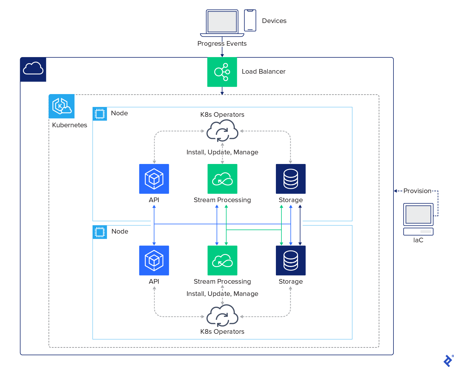
Our Structure With Most popular Programs
Though our design contains many elements, our system is comparatively easy within the total structure diagram:

Specializing in our Kubernetes atmosphere, we are able to merely set up our Kubernetes operators, Strimzi and YugabyteDB, and they’ll do the remainder of the work to put in the remaining companies. Our total ecosystem inside our Kubernetes atmosphere is as follows:

This deployment describes a distributed cloud structure made easy utilizing as we speak’s applied sciences. Implementing what was inconceivable as lately as 5 years in the past could solely take only some hours as we speak.
The editorial staff of the Toptal Engineering Weblog extends its gratitude to David Prifti and Deepak Agrawal for reviewing the technical content material and code samples offered on this article.
Additional Studying on the Toptal Engineering Weblog:
